UE4 landscape 使用 Texture Array
Landscape 使用 TextureArray
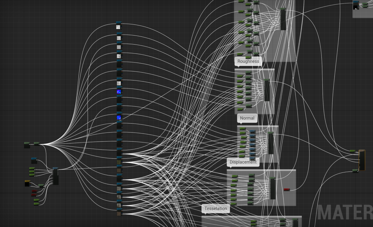
UE4 中 Landscape 一般会用到多张贴图来丰富地形地貌,例如下面是一个地形的例子:
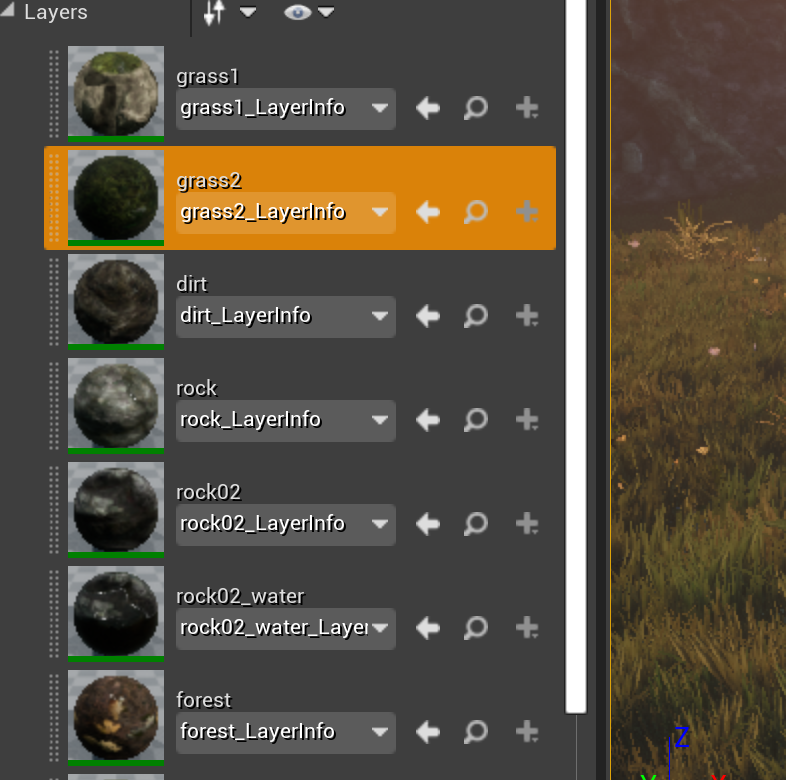
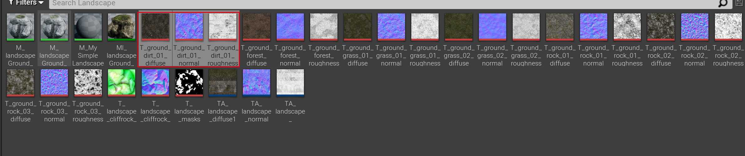
这个地形包含 7 个 Layer,每个 Layer 由三张贴图组成:
然后再加上权重图,在打安卓包时,就会出现如下错误:
UATHelper: Packaging (Android (ASTC)):   LogShaderCompilers: Display: shader uses 19
    samplers exceeding the limit of 16

UATHelper: Packaging (Android (ASTC)):   LogShaderCompilers: Display: shader uses 21
    samplers exceeding the limit of 16

UATHelper: Packaging (Android (ASTC)):   LogShaderCompilers: Display: shader uses 20
    samplers exceeding the limit of 16

UATHelper: Packaging (Android (ASTC)):   LogShaderCompilers: Warning: Failed to compile
    Material /Game/STF/Pack03-LandscapePro/Environment/Landscape/Landscape/
    M_landscapeGround_ajustabel.M_landscapeGround_ajustabel (MI:/Game/STF/
    Pack03-LandscapePro/Maps/TestMap.testmap:PersistentLevel.Landscape_1.
    LandscapeMaterialInstanceConstant_290) for platform GLSL_ES3_1_ANDROID,
    Default Material will be used in game.
然后真机上测试,地形会使用默认的材质,这显然不是我们想要的效果,要解决这个问题一个是减少贴图数量,另外一个办法就是使用 TextureArray。
1 TextureArray
在 UE4 4.26 版本,TextureArray 功能是默认开启的:
static TAutoConsoleVariable<int32> CVarAllowTexture2DArrayAssetCreation(
    TEXT("r.AllowTexture2DArrayCreation"),
    1,
    TEXT("Enable UTexture2DArray assets"),
    ECVF_Default
);
1.1 创建 TextureArray
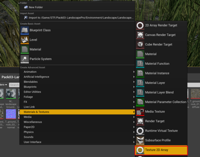
创建 TextureArray 的方法有两种,一种是直接创建,通过右键菜单,直接创建资源:
然后打开 TextureArray 资源,既可设置 TextureArray 中的贴图列表,注意:只有大小、格式一致的贴图才可以放到通一个 TextureArray 里,如果新增加的贴图不匹配,TextureArray 会自动删除最后一个新增的贴图。
bool UTexture2DArray::CheckArrayTexturesCompatibility()
{
    bool bError = false;

    if (TextureSourceCmp.GetSizeX() != SizeX || TextureSourceCmp.GetSizeY() != SizeY)
    {
        UE_LOG(LogTexture, Warning, TEXT("Texture2DArray creation failed.
            Textures %s and %s have different sizes."), *TextureName, *TextureNameCmp);
        bError = true;
    }

    if (PixelFormatCmp != PixelFormat)
    {
        UE_LOG(LogTexture, Warning, TEXT("Texture2DArray creation failed.
            Textures %s and %s have incompatible pixel formats."), *TextureName,
            *TextureNameCmp);
        bError = true;
    }

    return (!bError);
}
当然我们也可以选中一堆贴图,然后将选中的贴图直接生成一个 TextureArray 资源。
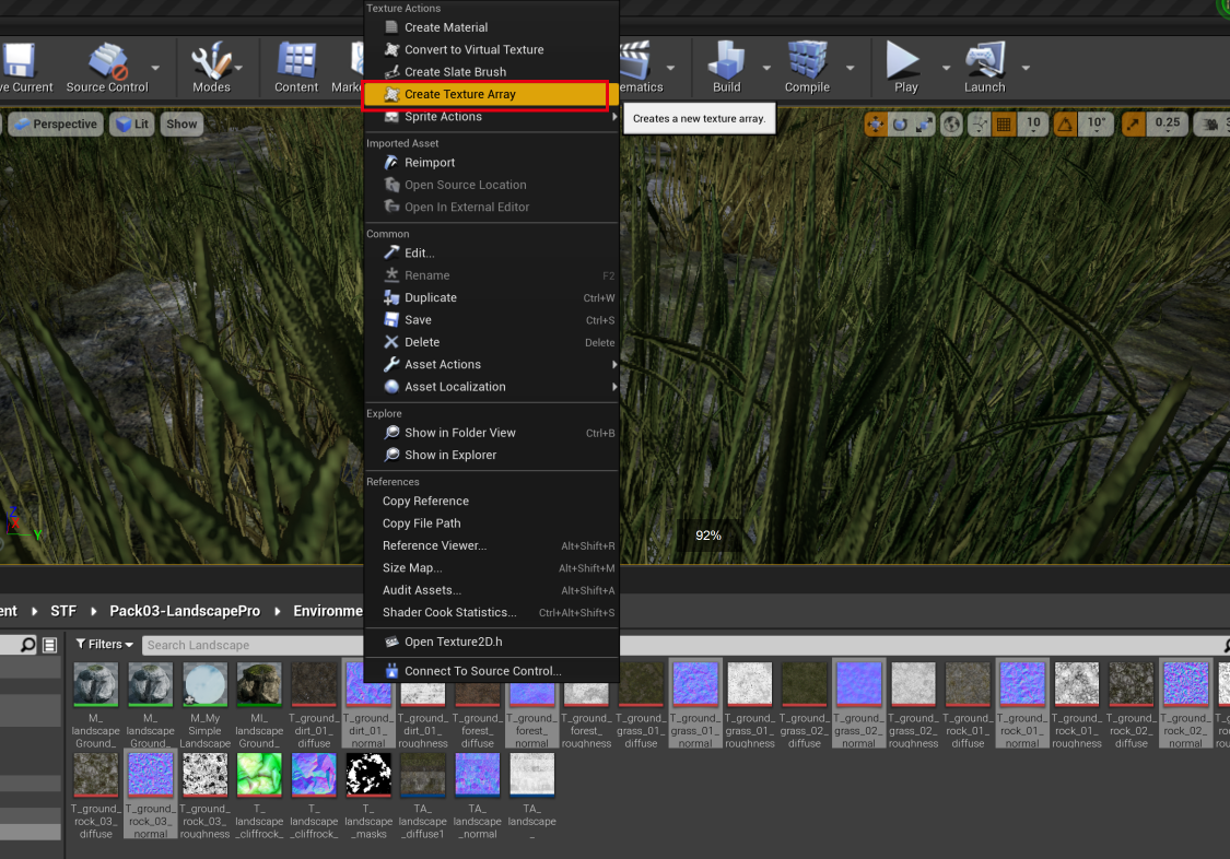
往 TextureArray 中增加贴图
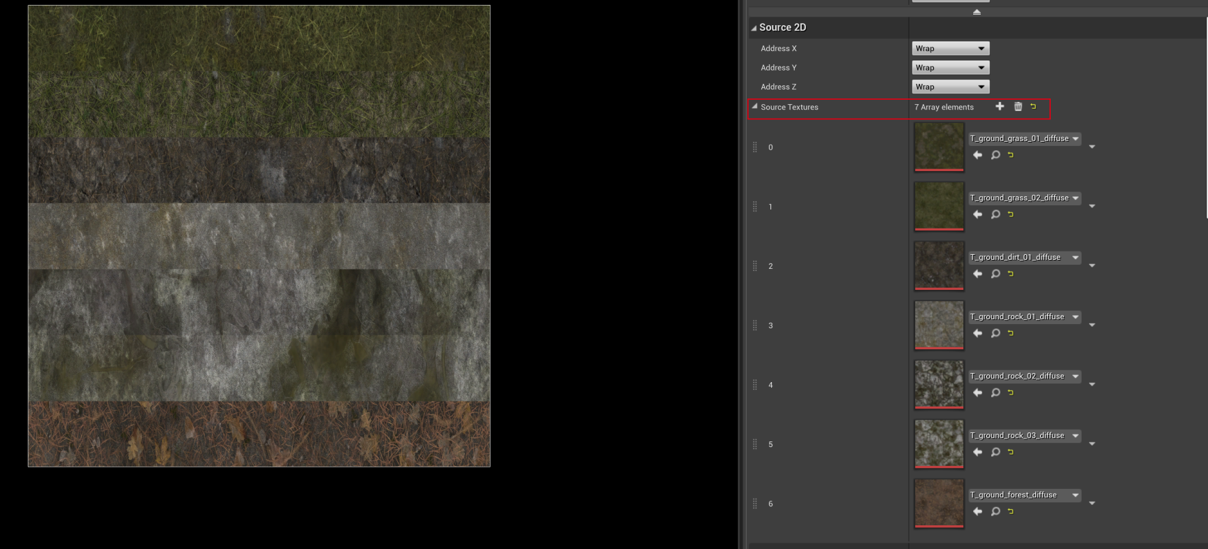
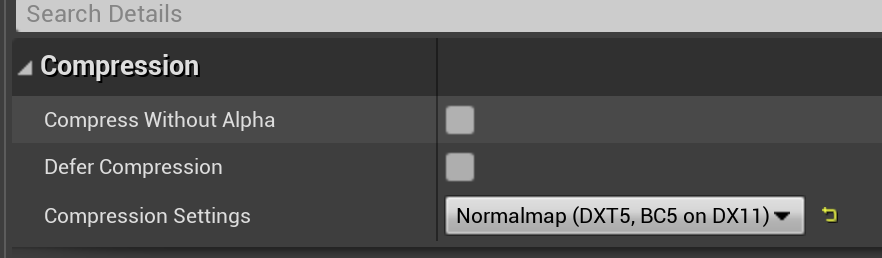
然后可以在编辑界面,修改 TextureArray 的一些属性:
- 开启 Mipmaps
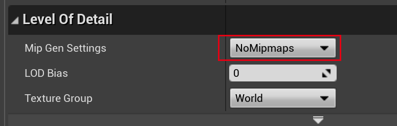
- 修改压缩格式
1.2 使用 TextureArray
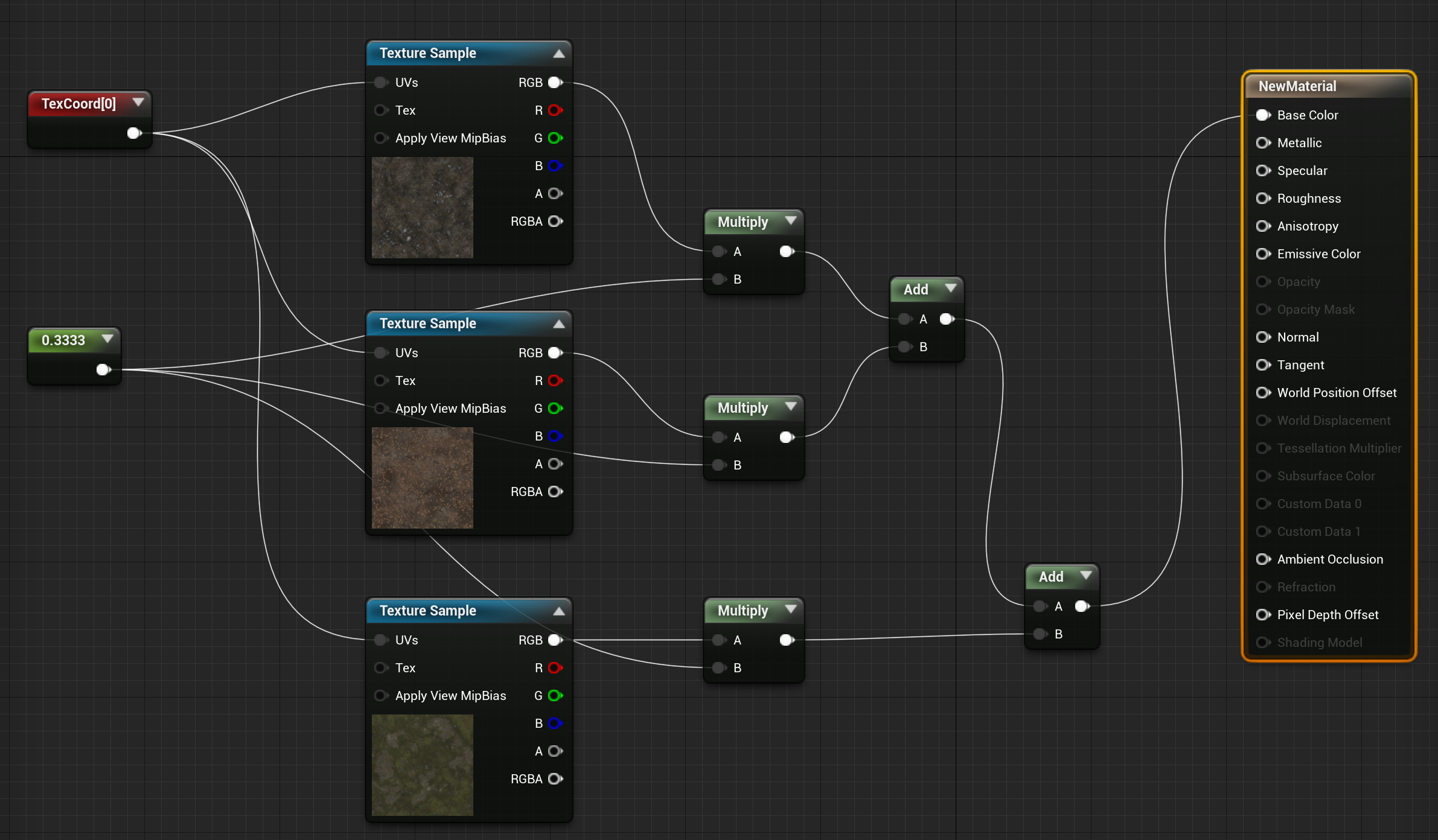
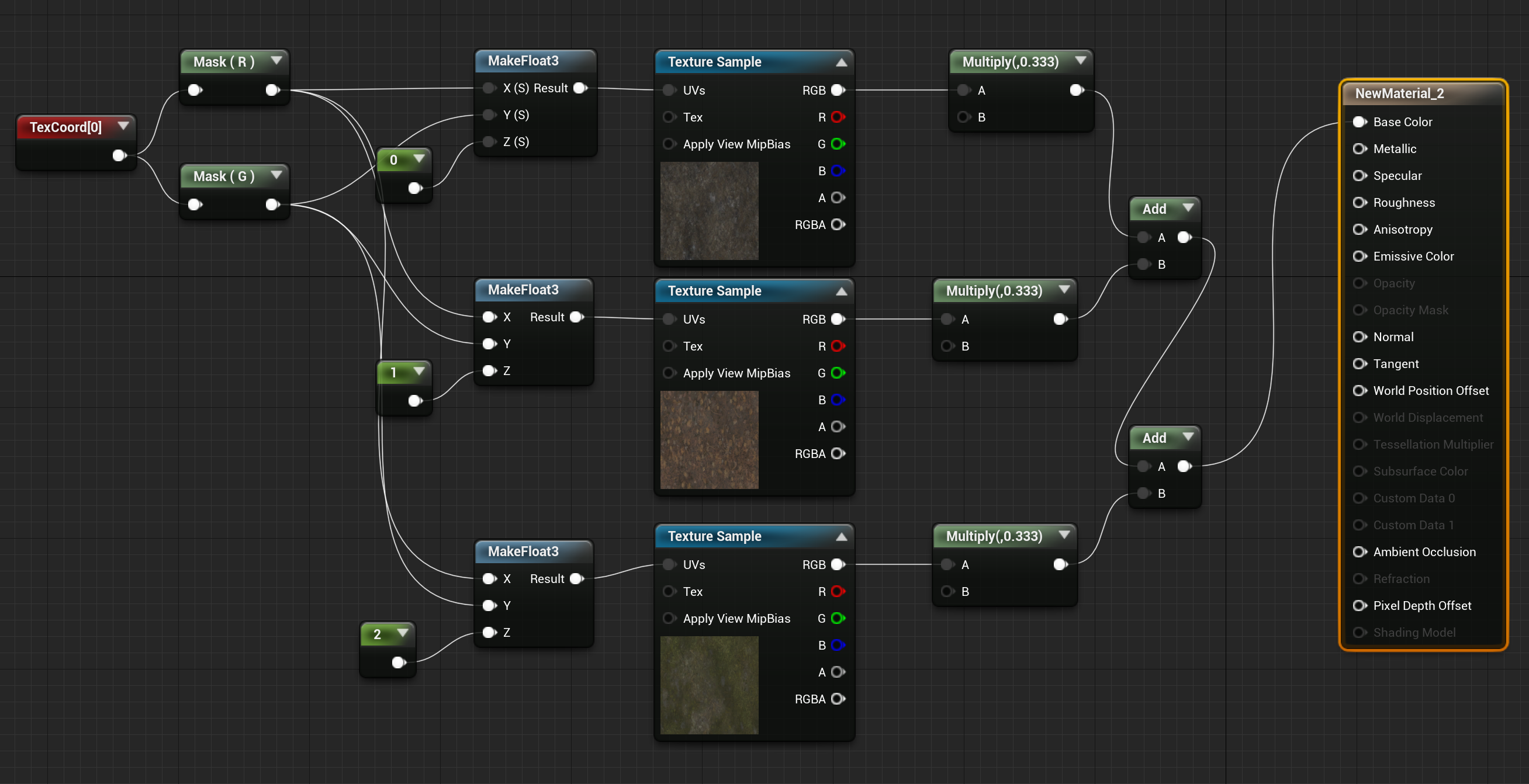
创建好 TextureArray 后,在材质中使用的方法如下,正常我们采样贴图做法如下:
使用 TextureArray 后,UVs 坐标不再是“二维”的了,而是“三维”,第三个分量需要指定采样 TextureArray 中第几张贴图的索引值(0 ~ num - 1):
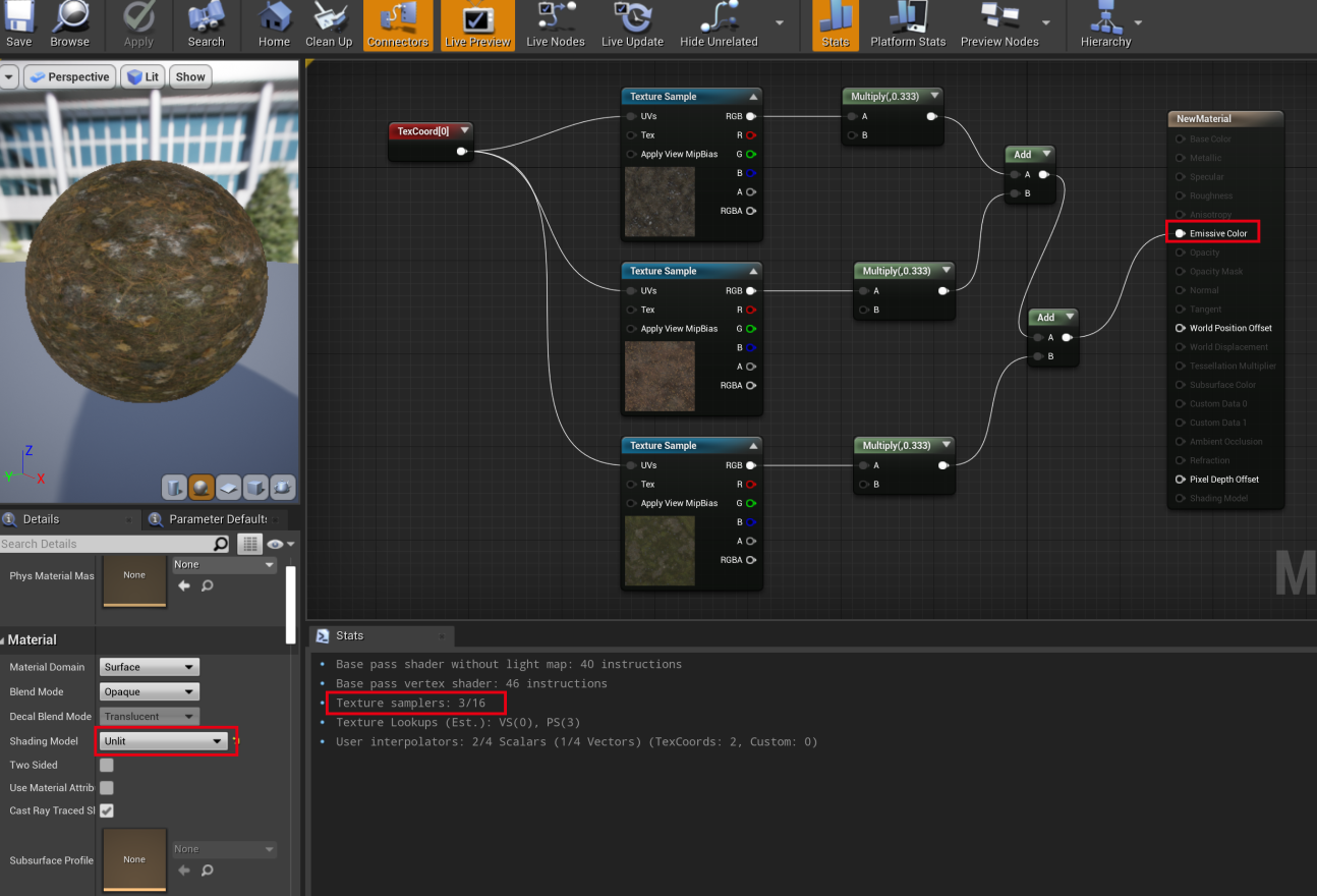
1.3 sample 对比
使用 unlit 模式下查看,不使用 TextureArray 的 Sample 数目为 3:
同样模式下查看,使用 TextureArray 的 Sample 数目为 1,纹理数就降下来了:
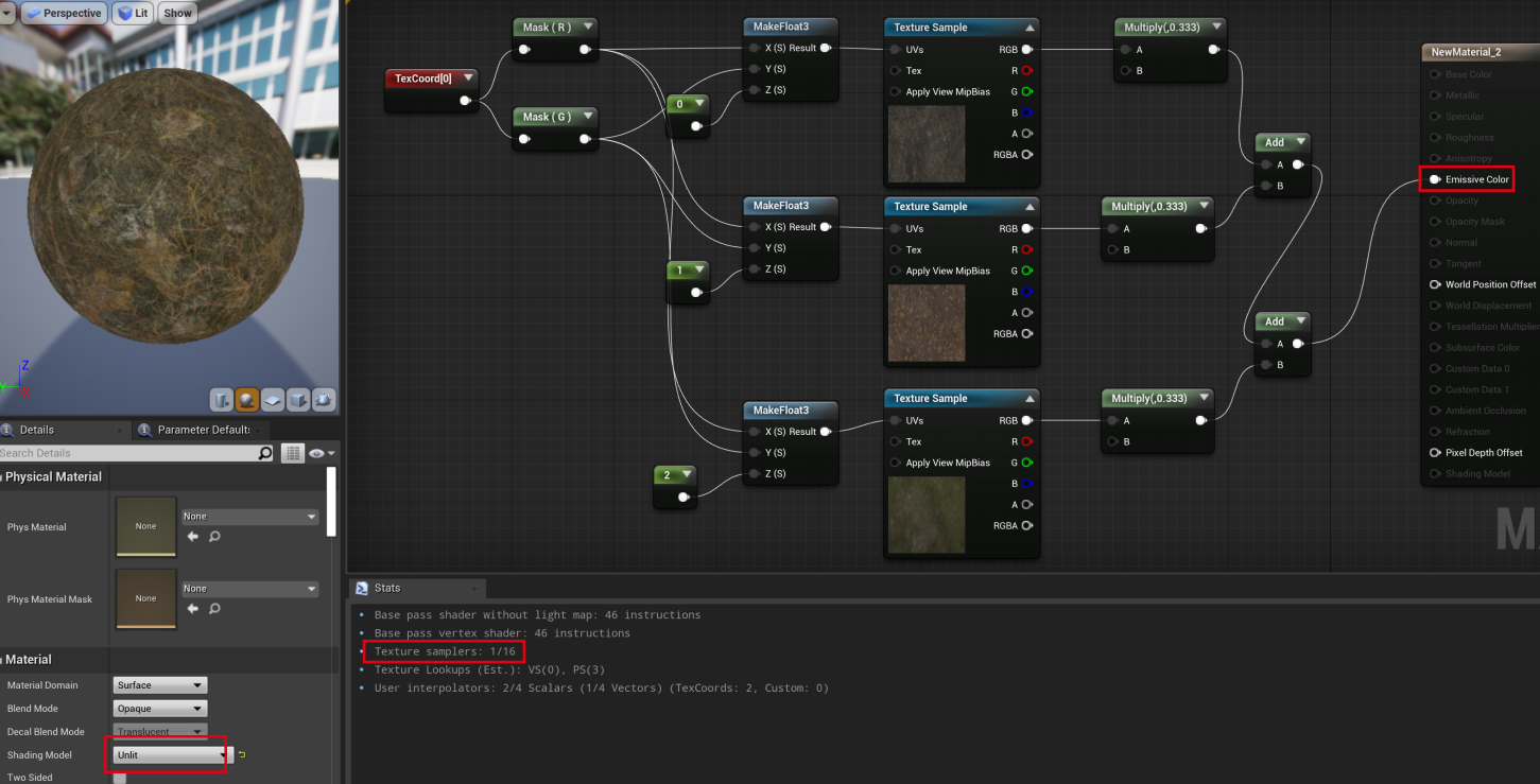
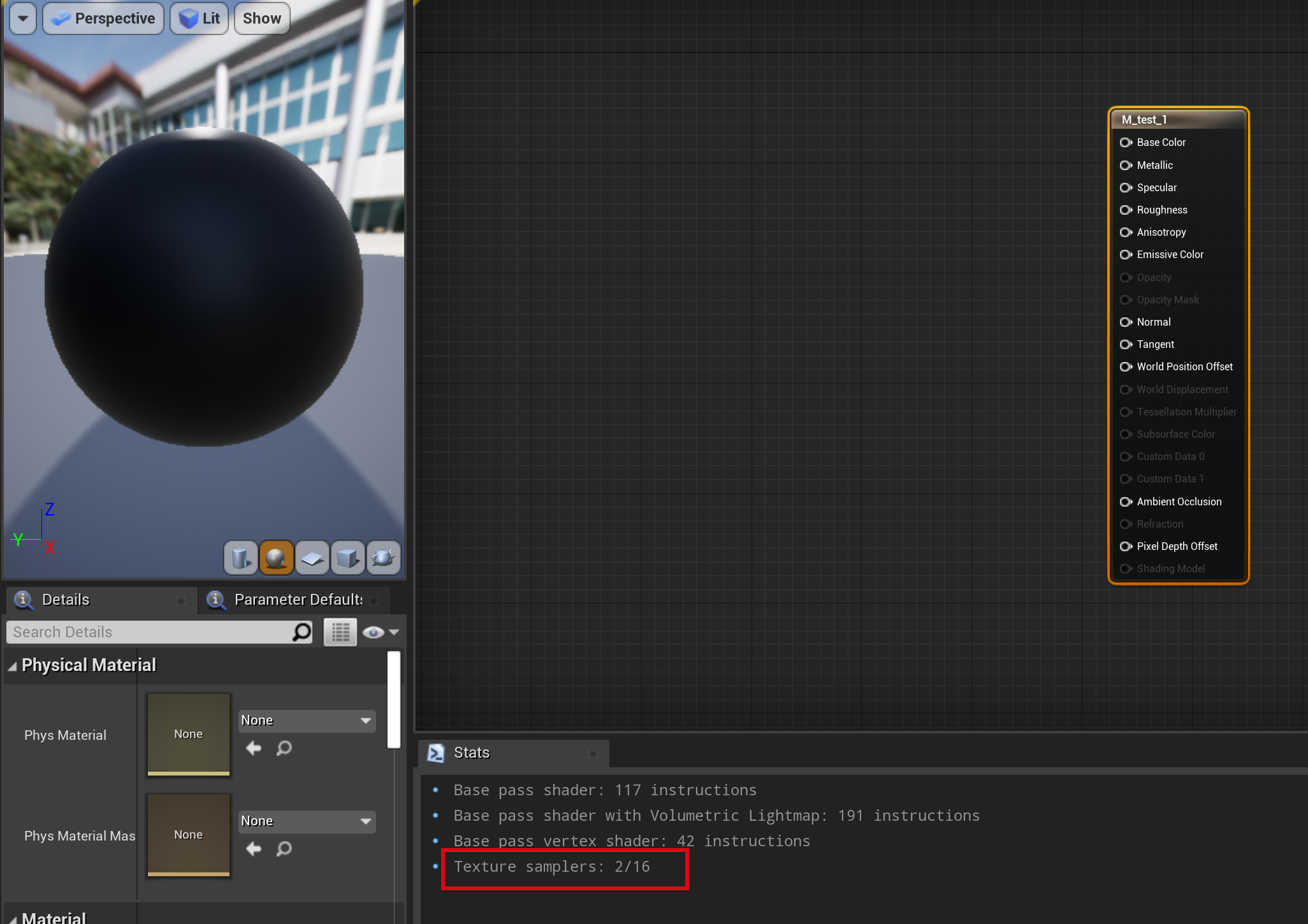
Lit 模式下,会有额外的 sample 次数,因此在 lit 模式下对应的 sample 不一样。
1.4 Texture2DArray 源码
FTextureResource* UTexture2DArray::CreateResource()
{
    const FPixelFormatInfo& FormatInfo = GPixelFormats[GetPixelFormat()];
    if (GetNumMips() > 0 && FormatInfo.Supported)
    {
        return new FTexture2DArrayResource(this,
            GetResourcePostInitState(PlatformData, GSupportsTexture2DArrayStreaming));
    }
}


void FStreamableTextureResource::InitRHI()
{
    CreateTexture();
}

class FTexture2DArrayResource : public FStreamableTextureResource
{
protected:

    void CreateTexture() final override
    {

        TRefCountPtr<FRHITexture2DArray> TextureArray =
            RHICreateTexture2DArray(FirstMip.SizeX, FirstMip.SizeY, FirstMip.SizeZ,
            PixelFormat, State.NumRequestedLODs, 1, CreationFlags, CreateInfo);

        TextureRHI = TextureArray;
    }
}

// 最终调用,然后转成平台相关接口
GDynamicRHI->RHICreateTexture2DArray(SizeX, SizeY,
    SizeZ, Format, NumMips, NumSamples, Flags, InResourceState, CreateInfo);
1.5 修改地形材质
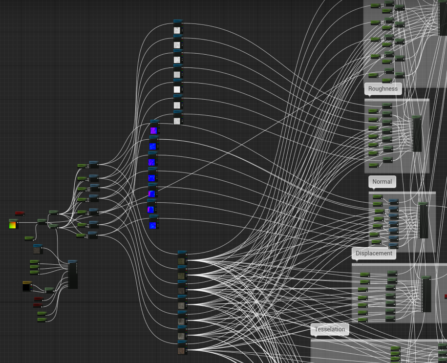
演示 Demo 的材质原先如下,将单独的贴图采样,修改成 TextureArray:
这里注意下贴图格式跟采样格式要匹配
贴图格式:
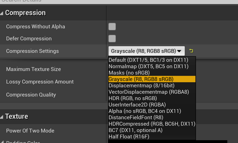
采样类型:
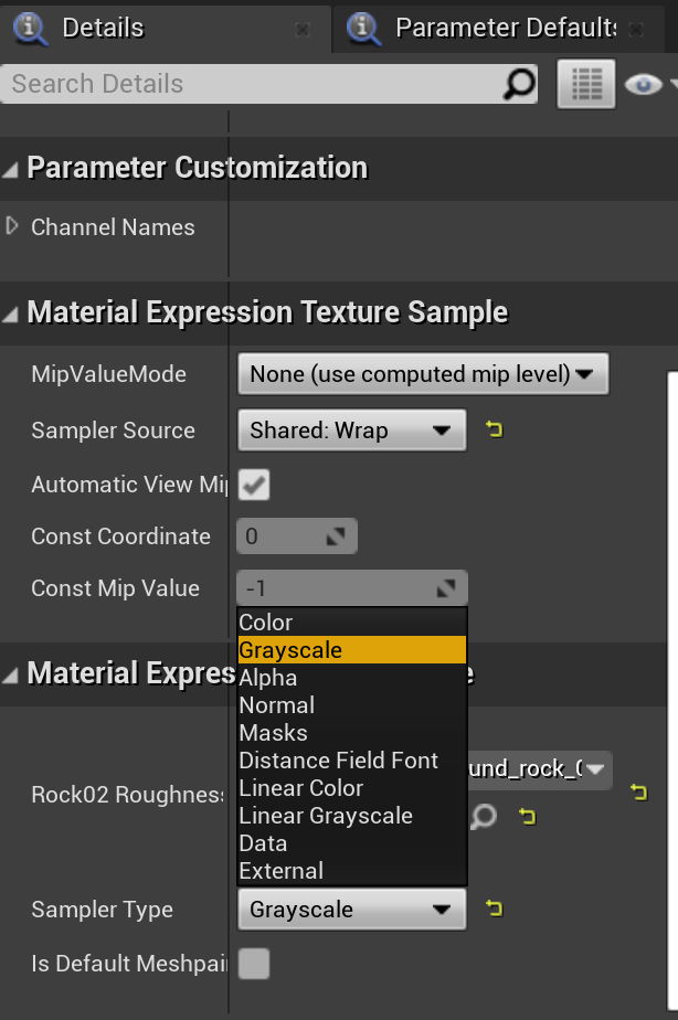
- 这里 Diffuse 采样需要使用 Color 类型
- Normal 采样使用 Normal 类型
- Roughness 这里给的是 Grayscale,因此采样类型需要改成 Grayscale
使用 TextureArray 修改之前的地形材质,打包然后在真机运行:
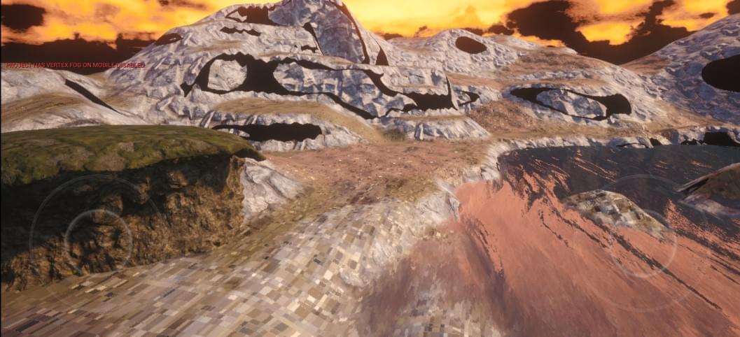
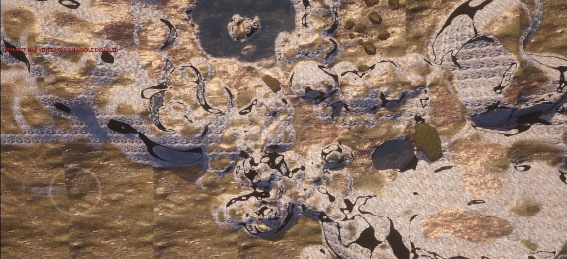
地形有部分区域出现了明显的方格,以及死黑区域。
1.6 解决方块问题
经过尝试,发现当靠近地形时,会有明显方块,但是远距离查看地形时,采样正确,猜测是顶点采样的 UV 出问题了
这是近处的效果:
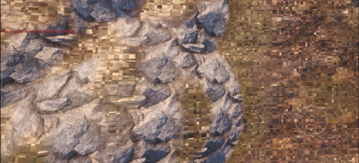
这是远处的效果:
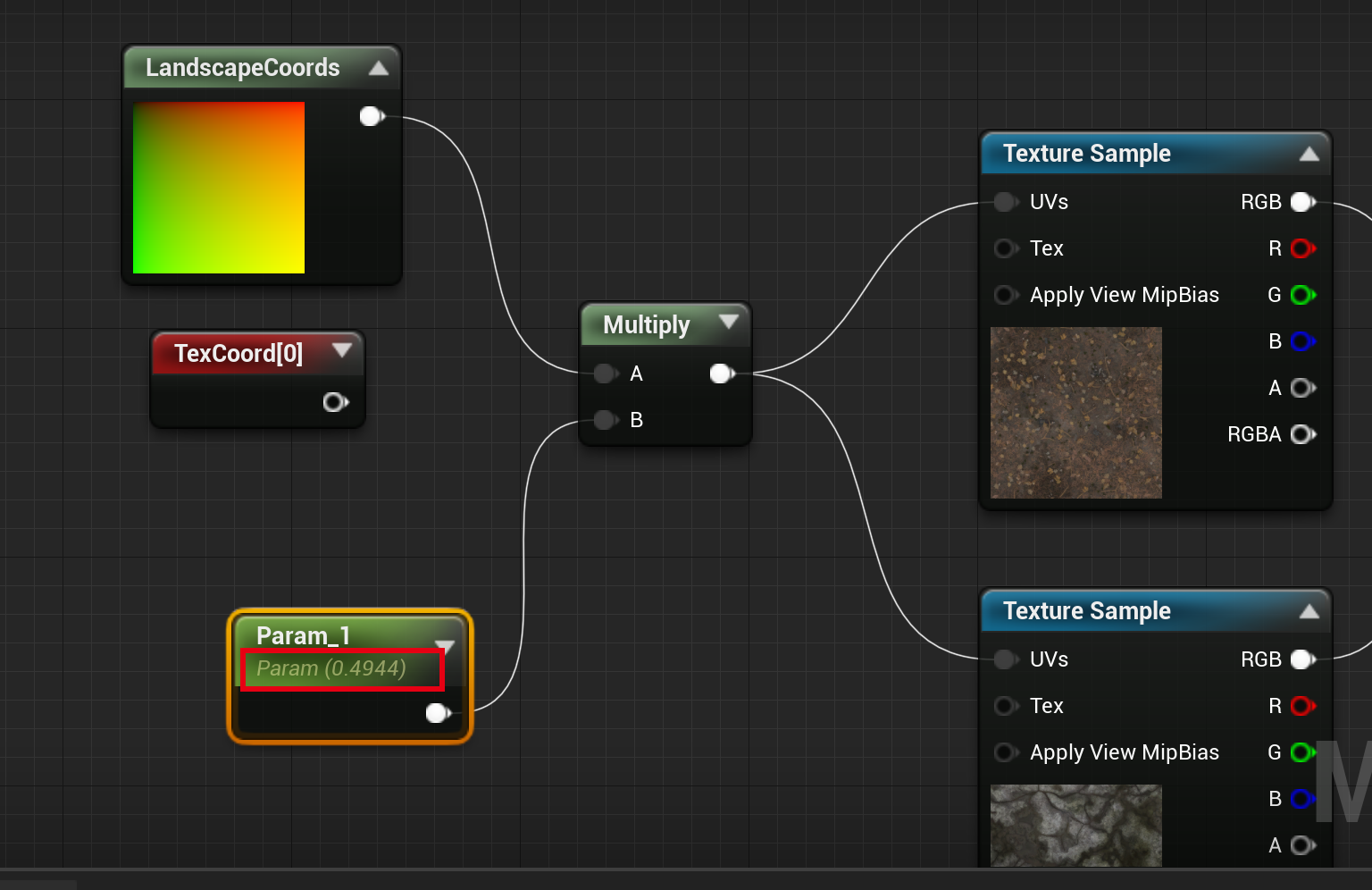
然后经过尝试发现,使用普通的 TextureCord 能正常显示贴图,然后使用了 LandscapeCorrd 然后配合 Divide,且当除数不为 1 时,就会出现方块:
于是查看 Landscape shader 源码,来尝试解决问题。
2 Landscape 材质
新建一个简单的地形材质,节点如下:
使用 RenderDoc 抓帧,可以看到在手机上,地形的 Shader 主要有两个:
MobileBasePassVertexShader.usf
MobileBasePassPixelShader.usf
2.1 Pixel Shader
通过 RenderDoc 截取到地形渲染的 PS shadner 代码如下,采样贴图的 UV 数据来源 TexCorrds
// Engine\Shaders\Private\MobileBasePassPixelShader.usf
void Main(
FVertexFactoryInterpolantsVSToPS Interpolants,
FMobileBasePassInterpolantsVSToPS BasePassInterpolants,
in float4 SvPosition
)
{
FPixelMaterialInputs PixelMaterialInputs;
FMaterialPixelParameters MaterialParameters = GetMaterialPixelParameters(
Interpolants, SvPosition);
// CalcMaterialParametersEx 定义
// 材质编辑器 -> windows -> shader code -> hlsl 导出代码
CalcMaterialParametersEx(MaterialParameters, PixelMaterialInputs,
In.SvPosition, ScreenPosition, In.bIsFrontFace, TranslatedWorldPosition,
TranslatedWorldPosition)
{
CalcPixelMaterialInputs(MaterialParameters, PixelMaterialInputs)
{
// Local7 Local8 其实就是将 TexCorrd X Y 分别取出来
float Local7 = dot(MaterialParameters.TexCoords[0].xy, float2 (0, 1));
float Local8 = dot(MaterialParameters.TexCoords[0].xy, float2 (1 ,0));
float2 Local9 = (1 * float2(Local8, Local7));
float2 Local10 = (Local9 + float2(0, 0));
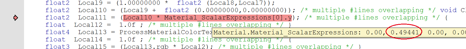
// 这里是材质编辑器中采样用到的 Param_1
float2 Local11 = (Local10 * Material_ScalarExpressions[0].y);
float4 Local13 = ProcessMaterialColorTextureLookup(Texture2DSampleBias(
Material_Texture2D_1, Material_Texture2D_1Sampler, Local11,
View_MaterialTextureMipBias));
}
}
}
TexCorrd 来源这个函数:
FMaterialPixelParameters GetMaterialPixelParameters(
    FVertexFactoryInterpolantsVSToPS Interpolants,
    float4 SvPosition)
{
    FMaterialPixelParameters Result = MakeInitializedMaterialPixelParameters();


#if NUM_MATERIAL_TEXCOORDS     // XY layer
    Result.TexCoords[0] = Interpolants.LayerTexCoord.xy;
#endif

    return Result;
}


// 这是 VS 到 PS 参数的类型定义:
struct FMobileShadingBasePassVSToPS
{
    struct FVertexFactoryInterpolantsVSToPS
    {
        float2  LayerTexCoord   : TEXCOORD0; // xy == texcoord
    };  FactoryInterpolants;

    struct FSharedMobileBasePassInterpolants
    {
        float4 PixelPosition    : TEXCOORD8; // xyz = world position, w = clip z
    }  BasePassInterpolants;


    float4 Position : SV_POSITION;
};
其中,FMobileShadingBasePassVSToPS 就是 VS 中的输出结果对象类型,接下来就看下 FactoryInterpolants 这个变量的生成过程。
2.2 顶点 Shader 逻辑
PS 里的输入就是从 C++ 中传入的 Index Buff
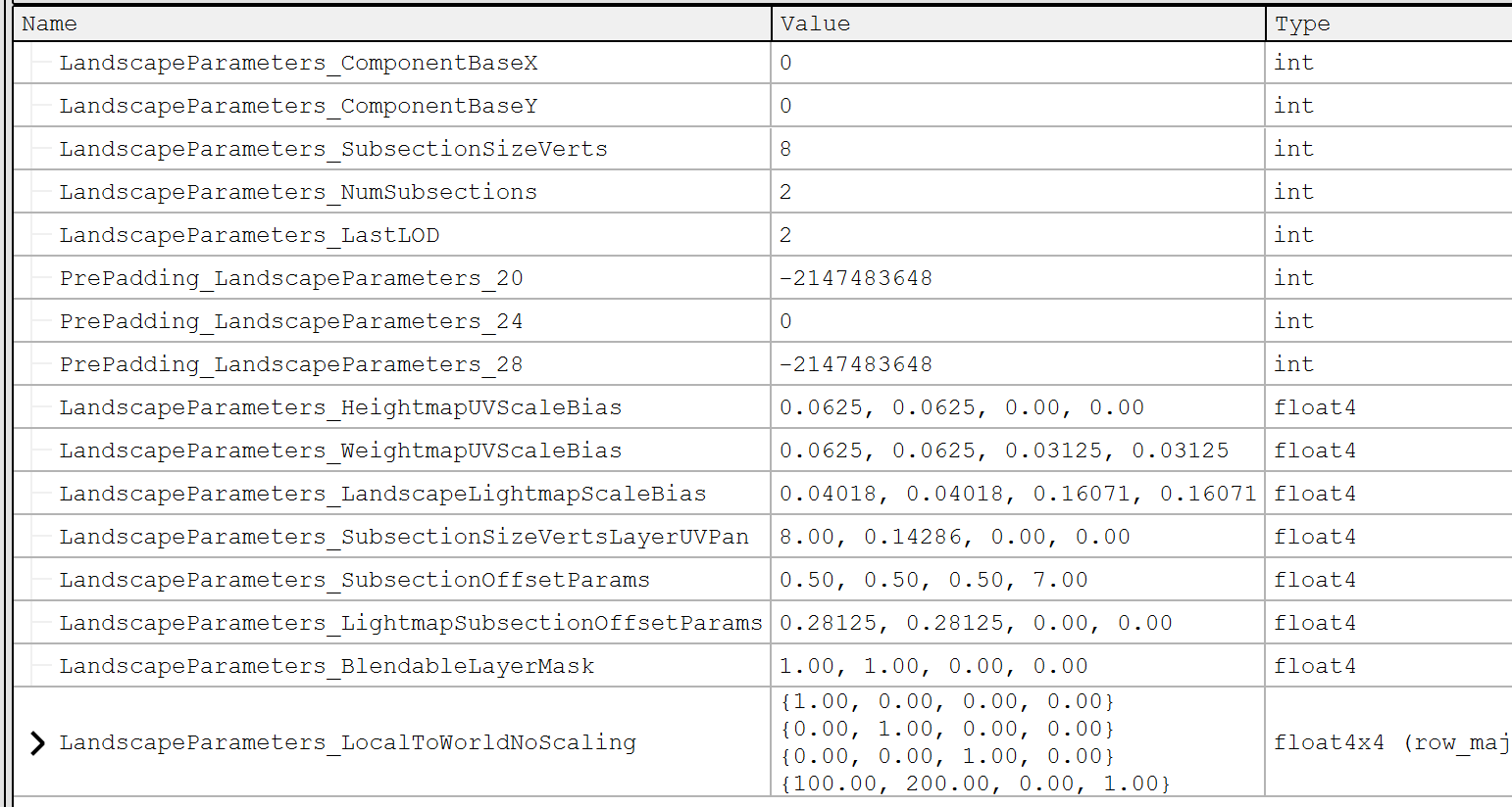
Uniform 主要包含两个
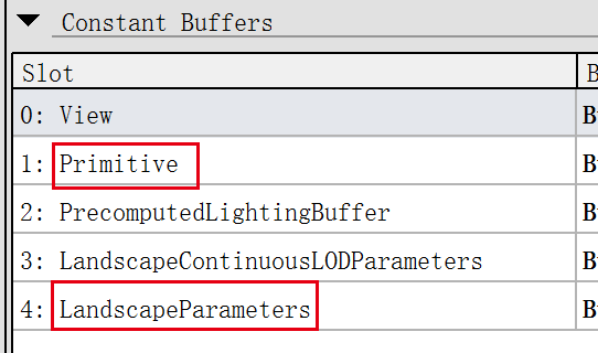
Primitive Uniform
Landscape Uniform
// Engine\Shaders\Private\MobileBasePassVertexShader.usf
void Main(
    FVertexFactoryInput Input,
    out FMobileShadingBasePassVSOutput Output
)
{
    // 这里之前讲过,如果不考虑 LOD 的情况,返回的坐标是每个顶点位置偏移
    FVertexFactoryIntermediates VFIntermediates = GetVertexFactoryIntermediates(Input);

    float4 WorldPositionExcludingWPO = VertexFactoryGetWorldPosition(Input,
        VFIntermediates);
}
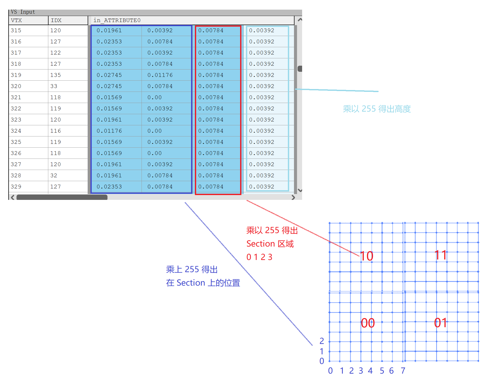
float3 GetLocalPosition(FVertexFactoryIntermediates Intermediates)
{
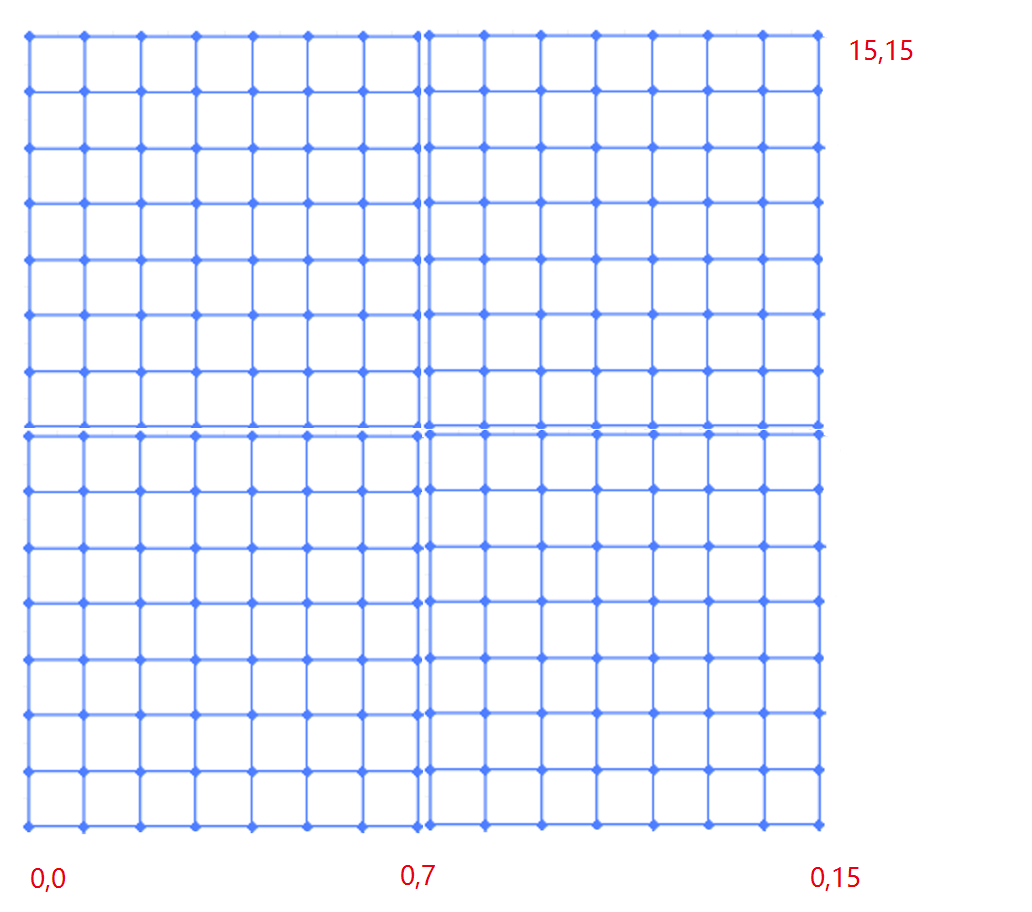
// LocalPosition 可以看做是每个顶点在各自 Section 中的 x y
// ZW 是对应 Section (0, 0) (0, 1) (1, 0) (1, 1)
// SubsectionOffsetParams : (0.5, 0.5, 0.5, 7),w 表示每个 Section 的大小
return INVARIANT(Intermediates.LocalPosition + float3(Intermediates.InputPosition.zw
* LandscapeParameters.SubsectionOffsetParams.ww,0));
}
float4 VertexFactoryGetWorldPosition(FVertexFactoryInput Input,
FVertexFactoryIntermediates Intermediates)
{
return INVARIANT(TransformLocalToTranslatedWorld(GetLocalPosition(Intermediates)));
}
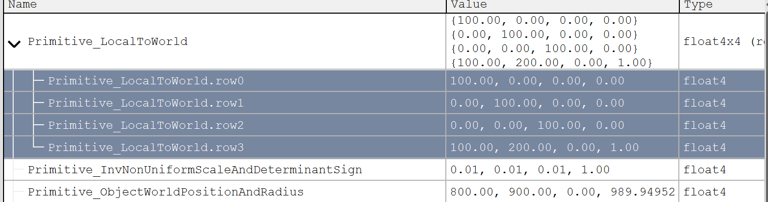
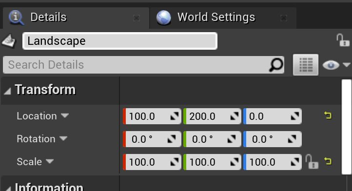
// Primive.LocalToWorld
// 100 0 0 0
// 0 100 0 0
// 0 0 100 0
// 100 200 0 1
float4 TransformLocalToTranslatedWorld(float3 LocalPosition)
{
float3 RotatedPosition = Primitive.LocalToWorld[0].xyz * LocalPosition.xxx
+ Primitive.LocalToWorld[1].xyz * LocalPosition.yyy
+ Primitive.LocalToWorld[2].xyz * LocalPosition.zzz;
return float4(RotatedPosition + (Primitive.LocalToWorld[3].xyz +
ResolvedView.PreViewTranslation.xyz),1);
}然后就能计算出每个顶点的坐标了,我们主要关注的是 PS 中采样用到的 TexCoord_0,因此继续查看这个变量的计算过程。
VS 向 PS 传参的类型是 FMobileShadingBasePassVSOutput
#define FMobileShadingBasePassVSOutput FMobileShadingBasePassVSToPS
#define VertexFactoryGetInterpolants VertexFactoryGetInterpolantsVSToPS
// Engine\Shaders\Private\MobileBasePassVertexShader.usf
// VS Main 函数入口
void Main(
FVertexFactoryInput Input
, out FMobileShadingBasePassVSOutput Output
)
{
// 省去一堆代码
// 之前的坐标计算
float4 WorldPositionExcludingWPO = VertexFactoryGetWorldPosition(Input,
VFIntermediates);
// FactoryInterpolants 的生成在这里
Output.FactoryInterpolants = VertexFactoryGetInterpolants(Input,
VFIntermediates, VertexParameters);
}
// Engine\Shaders\Private\LandscapeVertexFactory.ush
FVertexFactoryInterpolantsVSToPS VertexFactoryGetInterpolantsVSToPS(
FVertexFactoryInput Input,
FVertexFactoryIntermediates Intermediates,
FMaterialVertexParameters VertexParameters)
{
FVertexFactoryInterpolantsVSToPS Interpolants;
Interpolants = (FVertexFactoryInterpolantsVSToPS)0;
// 随后计算 TexCorrd
FLandscapeTexCoords LandscapeTexCoords = GetLandscapeTexCoords(InputPosition,
Intermediates)
#if (ES3_1_PROFILE)
Interpolants.LayerTexCoord = LandscapeTexCoords.LayerTexCoord;
Interpolants.WeightMapTexCoord = LandscapeTexCoords.WeightMapTexCoord;
#endif
}
FLandscapeTexCoords GetLandscapeTexCoords(
FVertexFactoryInput Input,
FVertexFactoryIntermediates Intermediates)
{
FLandscapeTexCoords Result;
// 根据输入跟 Uniform 中的值,输出 Texcorrd
// LocalPosition : 0,0 ~ 7,7
// SubsectionSizeVertsLayerUVPan : 8, 0.14286, 0, 0
// InputPosition.zw : 0,0 ~ 1,1
// SubsectionOffsetParams : 0.5, 0.5, 0.5, 7
Result.LayerTexCoord.xy = Intermediates.LocalPosition.xy +
LandscapeParameters.SubsectionSizeVertsLayerUVPan.zw +
Intermediates.InputPosition.zw * LandscapeParameters.SubsectionOffsetParams.ww;
return Result;
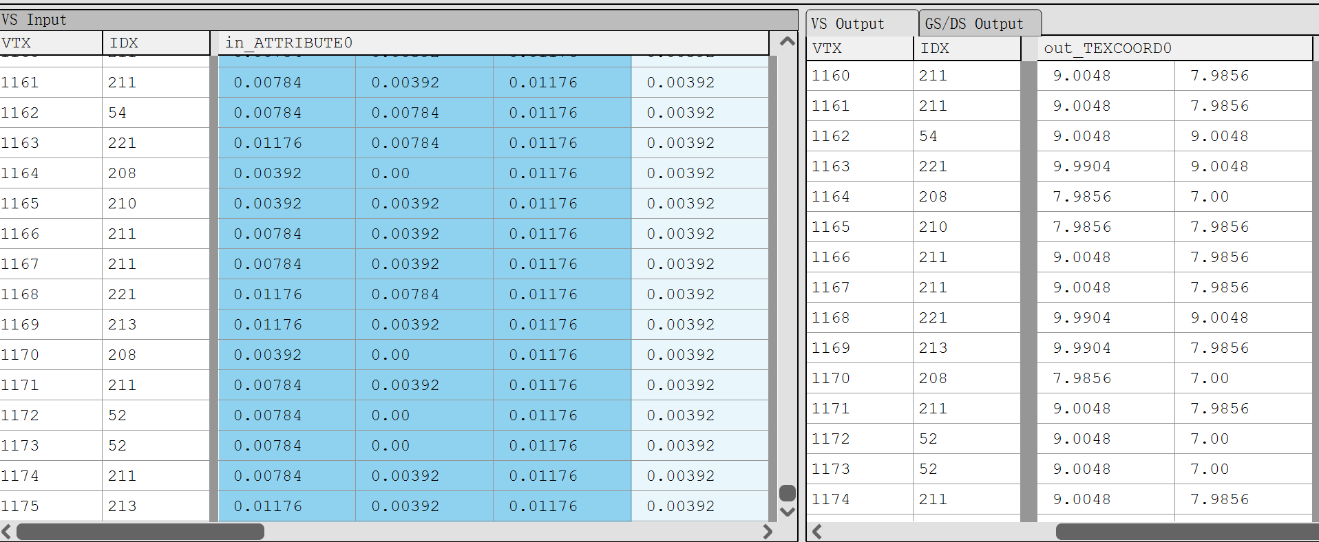
}可以得出计算得出的 LayerTexCoord 其实就是 Landscape 中每个顶点对应在 Component 中的位置。最终计算出来的 TextCorrd_0 结果如下图,可以看到计算得出的 UV 其实大部分都会大于 1,采样的时候贴图设置的是 Wrap,因此最终地形上的纹理会平铺。
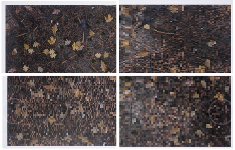
下面是不同方式采样贴图,跟是否使用高精度的对照图,左边列的是使用 TextureCoord 采样贴图的(Corrd),右边列是使用 LandScapeCorrd 方式(LandScape),上面一排是未勾选高精度(normal),下面一排是勾选了高精度的(hp)。
而且离地形远点越远,偏差越大
RenderDoc 抓帧,FS 输出的 TextureCorrd0 数据完全一致。顶点 Shader 没问题,只能继续分析 Pixel Shader,通过 RenderDoc 抓取 PS 代码发现:
//  LandscapeCorrd
highp vec2 v31 = vec2(1.0, 0.0);
float h32 = dot(in_TEXCOORD0, v31);
vec2 v30;
v30.x = h32;
highp vec2 v33 = vec2(-0.0, 1.0);
float h34 = dot(in_TEXCOORD0, v33);
v30.y = h34;
vec2 v35 = v30 * _30.pu_m[2].xx;
highp float f36 = 0.5;
highp float f5 = f36;


highp vec2 v38 = v35;
highp vec4 v39 = _30.pu_m[0];
float h40 = dot(v7, v39);
highp vec2 v41 = v35;
highp vec4 v42 = _30.pu_m[1];
float h43 = dot(v7, v42);
vec3 v37 = clamp((texture(Material_Texture2D_0, v38).xyz * vec3(h40)) +
    (texture(Material_Texture2D_1, v41).xyz * vec3(h43)), vec3(0.0), vec3(1.0));

// TextureCord
highp float f31 = _30.pu_m[2].x;
vec2 v32 = in_TEXCOORD0 * vec2(f31);
vec2 v30 = v32;
highp float f33 = 0.5;
highp float f5 = f33;
highp vec2 v35 = v30;
highp vec4 v36 = _30.pu_m[0];
float h37 = dot(v7, v36);
highp vec2 v38 = v30;
highp vec4 v39 = _30.pu_m[1];
float h40 = dot(v7, v39);
vec3 v34 = clamp((texture(Material_Texture2D_0, v35).xyz * vec3(h37)) +
    (texture(Material_Texture2D_1, v38).xyz * vec3(h40)), vec3(0.0), vec3(1.0));
精简后得到的 Diff 如下:
//  LandscapeCorrd
highp vec2 v31 = vec2(1.0, 0.0);
float h32 = dot(in_TEXCOORD0, v31);
vec2 v30;
v30.x = h32;
highp vec2 v33 = vec2(-0.0, 1.0);
float h34 = dot(in_TEXCOORD0, v33);
v30.y = h34;
vec2 v35 = v30 * _30.pu_m[2].xx;

// TextureCord
highp float f31 = _30.pu_m[2].x;
vec2 v32 = in_TEXCOORD0 * vec2(f31);
vec2 v30 = v32;
两种方式只是最终获取 UV 的计算方式不同,尝试修改 Shader 代码,将出现偏差的代码改成:
// LandscapeCorrd
highp vec2 v31 = vec2(1.0, 0.0);
float h32 = dot(in_TEXCOORD0, v31);
vec2 v30;
v30.x = h32;
highp vec2 v33 = vec2(-0.0, 1.0);
float h34 = dot(in_TEXCOORD0, v33);
v30.y = h34;
- vec2 v35 = v30 * _30.pu_m[2].xx;
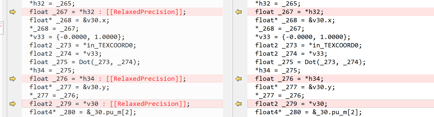
+ vec2 v35 = in_TEXCOORD0 * _30.pu_m[2].xx;应用修改后,采样完全正确,因此定位到问题是计算 UV 坐标阶段,然后分别使用 Debug 功能,获取最终反编译后的代码,对比后发现如下差异:
// 修改后                           // 修改前
*_277 = _276;                      *_277 = _276;
float2 _279 = *in_TEXCOORD0;       float2 _279 = *v30 : [[RelaxedPrecision]];
发现修改前后差异是变量 V30 后有个: RelaxedPrecision,不强制驱动使用fp16计算,具体解析在此链接
然后尝试回退代码,将其中用到的变量都改成高精度:
highp vec2 v31 = vec2(1.0, 0.0);
- float h32 = dot(in_TEXCOORD0, v31);
+ highp float h32 = dot(in_TEXCOORD0, v31);
- vec2 v30;
+ highp vec2 v30;
v30.x = h32;
highp vec2 v33 = vec2(-0.0, 1.0);
- float h34 = dot(in_TEXCOORD0, v33);
+ highp float h34 = dot(in_TEXCOORD0, v33);
v30.y = h34;
vec2 v35 = v30 * _30.pu_m[2].xx;
反编译后的代码 diff 如下:
应用修改后,效果也完全正确,因此,当使用 LandscapeCord 节点获取 UV 坐标时,UE4 编译生成的代码,会对变量做优化,增加 RelaxedPrecision,这就导致在不同的设备上,运行计算的精度是不确定的,因此在使用该节点时需要注意。
最后抓帧查看 Landscape 开启高精度后的 ps 代码,来验证一下之前的问题:
// 开启高精度后,v13 被定义成了 highp,对比未开启高精度的 v30
highp vec2 v13;
v13.x = dot(in_TEXCOORD0, vec2(1.0, 0.0));
v13.y = dot(in_TEXCOORD0, vec2(-0.0, 1.0));
highp vec2 v14 = v13 * _16.pu_h[7].xx;
highp vec3 v15 = clamp((texture(Material_Texture2D_0, v14).xyz *
    vec3(dot(v5, _16.pu_h[5]))) + (texture(Material_Texture2D_1, v14).xyz *
    vec3(dot(v5, _16.pu_h[6]))), vec3(0.0), vec3(1.0));